Our present strategy is for nations to meet COP26 commitments for net-zero by 2050, but still rely in-part on carbon-emitting technologies and industries to satisfy our energy, transport and construction demands. Approximately 87% of human carbon dioxide (CO2) release is from burning fossil fuels for transportation or for the generation of electricity and heat [1], with other significant processes being related to cement and steel manufacture, waste disposal and biofuel production and combustion. For each of these industries, carbon capture technology can be retrofitted, or designed-in, to become a part of the process. Not only will this technology drastically reduce carbon emissions to meet social and legislative requirements, but if CO2 can be seen as a product rather than a waste (in terms of utilisation or carbon trading), it might also be implemented for economic benefit.
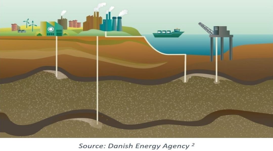
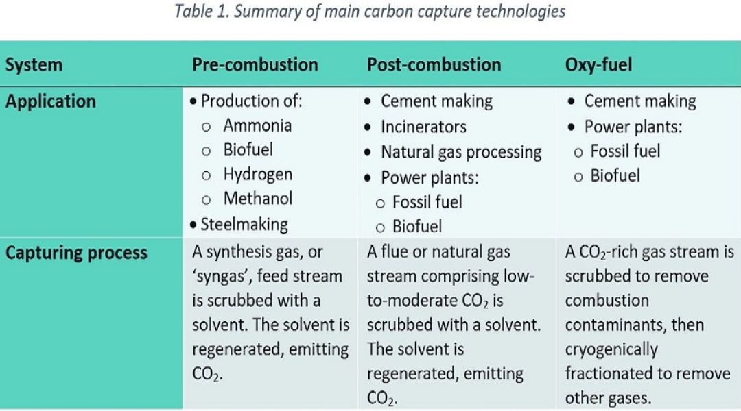
Whilst there is a broad range of technologies and derivatives for carbon capture, three main categories are commonly referred to for industrial carbon capture processes: pre-combustion, post-combustion & oxy-fuel. These technologies are summarised in Table 1 and then expanded under the relevant headings below. A given technology might be chosen depending on the type of industrial process, the composition of the stream to be treated and whether the application relates to a new-build facility or retrofit of an existing plant. Once the CO2-rich stream has been captured, it is then compressed, liquified into a ‘dense phase’ and then transported to a site for permanent sub-surface sequestration via pipeline or road/rail car.
Regardless of the chosen technology being employed, there are challenges for materials design and corrosion control techniques that need to be considered as a means to design a system that is safe, reliable and cost-effective. This should involve a corrosion assessment of the facility to identify potential causes of degradation and how to identify the early onset of these damage mechanisms through monitoring and targeted inspection.
Carbon Capture Technology
Pre-combustion
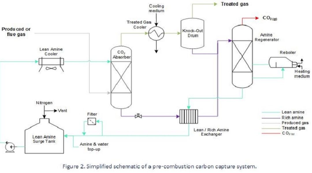
Gasification of liquid and solid fuels, along with methane (CH4) reforming, generate synthetic gas (i.e., syngas) for the production of hydrogen (H2) or as part of wider industrial processes such as steelmaking and chemical production facilities for ammonia, methanol & biofuel. The composition of syngas can vary depending upon its source (i.e., natural gas, liquid hydrocarbons, coal or biomass), but typically comprises varying amounts of carbon monoxide (CO), H2, CO2 and CH4. The most common pre-combustion capture process converts CO within the syngas into CO2 and then extracts this by using a physical solvent (i.e., physical gas absorption according to Henry’s Law) upstream of H2 users (e.g., reactors, gas turbines, iron reduction plants, etc.).
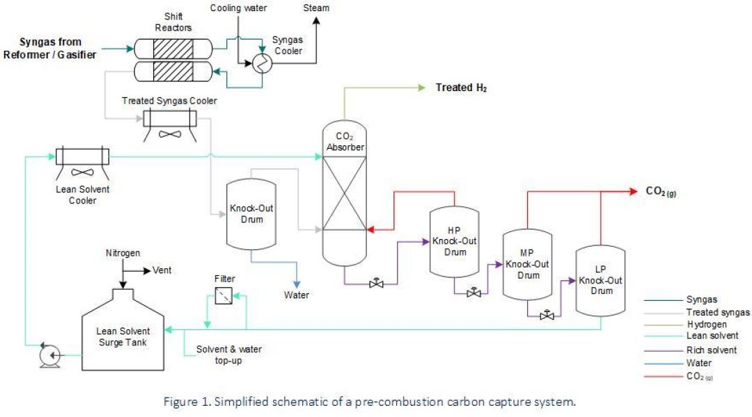
Pre-combustion carbon capture is easier and more efficient than the post-combustion process due to the high partial pressure of CO2 within the treated syngas stream. However, process conditions associated with this technology involve a broad range of operating conditions and – depending on the fuel source for syngas generation – can include a range of harmful contaminants.
Various damage mechanisms for consideration are listed below:
- Sulphidation, High-Temperature Hydrogen Attack (HTHA) and decarburisation of carbon and low-alloy steel parts operating at elevated temperatures (i.e., from syngas-generating equipment through to the shift reactors).
- CO Stress-Corrosion Cracking (CO-SCC), or corrosion by carbonyl formation, of carbon steel and low-alloy steel pressure systems handling CO at moderate-to-low temperatures.
- Low-temperature environments bearing acid gases such as CO2 are conducive to carbonic acid corrosion, and if hydrogen sulphide (H2S) is present as a contaminant then sour service requirements should be met in order to avoid cracking mechanisms such as Sulphide Stress Cracking (SSC) and Hydrogen Induced Cracking (HIC).
- Hydrogen embrittlement and hydrogen cracking need to be considered within H2 service for steels of various strength categories, where there has been no Post-Weld Heat Treatment (PWHT), or within thick-walled pressure equipment.
- Localised corrosion in solvent lines due to vapour flashing. This happens when rich solvent releases CO2 before reaching the Knock-Out (KO) drums.
Post-combustion
In scenarios where a vapour stream comprises a modest amount of CO2, such as a ‘post-combustion’ flue gas stream, or, when ‘sweetening’ an un-treated natural gas stream, a chemical solvent may be used to extract CO2. Absorption takes place by chemical bonding with the solvent – typically comprising amines – and downstream of this the chemically bound gas is heated and depressurised to release it from the solvent.
Carbon capture using amine solvent is well established and effective but involves a relatively expensive asset inventory and is notorious for corrosion-related problems that are complex to solve and sometimes unobserved. Economies are made during design by employing inexpensive materials to handle fluids which are benign under the intended operating conditions but can rapidly change to a corrosive regime if subject to process changes, contamination or a failure to maintain chemical constituents.
One of the reasons for the high failure rate is their complexity and several driving factors contribute to corrosion problems, making it challenging to identify the root cause. Every system of this type is unique due to the feedstock properties, design conditions and operating philosophy. However, corrosion issues can be well-managed with the right level of plant information and engineering experience.
Some of the most common causes of degradation within post-combustion / gas sweetening systems are as follows:
- Localised corrosion in rich solvent lines due to vapour flashing. This happens when rich solvent releases CO2 before reaching the regenerator, where this release is designed to occur.
- Amine SCC in carbon steel solvent piping where there has been no PWHT.
- Degradation of the chemical solvent: Virgin solvent contains less than 1% of heat-stable salts, but these build up over time due to continuous recycling. Levels of 2- 3% and higher can lead to corrosion on the lean solvent circuit. Other causes of solvent degradation are high temperatures and contaminant ingress.
- High fluid velocity or turbulence causes erosion-corrosion of piping and equipment. This process condition can occur after control valves, or in reboiler return lines.
Oxy-fuel
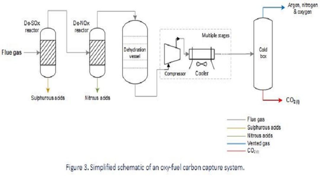
Where combustion facilities are used for power generation, or as part of cement manufacturing processes, the efficiency of combustion can be greatly improved using high-purity oxygen, or a mixture of oxygen and recirculated flue gas, instead of air. This reduces both fuel consumption and heat loss whilst generating a flue gas stream that comprises a very high proportion of CO2. Having a flue gas rich in CO2 means that there is less energy required to separate it out from the other constituents.
The process setup will vary depending on the fuel source, regulatory requirements and geotechnical aspects, but typically carbon capture is achieved by first removing contaminants such as sulphurous oxides (SOx) and nitrous oxides (NOx) from the flue gas, before it’s dehydrated and then subject to fractional distillation to vent remaining contaminants such as argon, nitrogen and oxygen from a high-purity dense-phase CO2 stream.
Carbon capture from an oxy-fuel process is the least mature method to-date and the equipment needed to meet local requirements will vary. At present, only pilot projects are running to demonstrate proof-of-concept, and so there is limited industrial experience associated with in-service degradation; however, the process conditions are assessed to predict which damage mechanisms are expected and where they’re likely to manifest as part of materials design and in-service inspection planning.
Anticipated causes of failure within an oxy-fuel carbon capture process are as follows:
- High corrosivity due to flue gas corrosion will drive the use of high-alloy materials in the early part of the process, where water is condensing in the presence of acid gases and sulphurous products. Localised attack may still initiate under deposits.
- Halide-induced SCC of stainless steels may be of concern in wet flue gas service where materials are exposed to water, oxygen and chloride or fluoride contaminants.
- Cryogenic conditions can reduce the toughness of certain materials and condense mercury from a vapour phase and so considerations for low temperature embrittlement and liquid metal embrittlement of susceptible materials should be evaluated.
- Water contaminant carried past the dehydration vessel due to upset conditions can lead to carbonic acid corrosion in the dense-phase CO2.
How Vysus Group approaches corrosion problems within carbon capture systems
Carbon capture systems can be exposed to highly corrosive fluids and are often complex to troubleshoot when they exhibit corrosion issues. However, Vysus Group has worldwide experience in such systems in a diverse range of applications. Drawing on this global experience base, Vysus Group has the technical expertise to mitigate or resolve corrosion in carbon capture systems. We work together with our clients to investigate, analyse and make recommendations using a proven engineering process:
- Develop an understanding of root causes by collection and analysis of plant information, design conditions and process changes
- Diagnose failure mechanisms and contributing factors
- Make recommendations like material upgrades, fluid monitoring, or setting new process conditions
Contact Vysus Group for help to solve your corrosion problems associated with carbon capture process systems.
Related Services